

This blog is about my 2nd semester lab project at Department of Electronic and Telecommunication Engineering at University of Moratuwa. The task was to design and implement an alarm clock with the following functions.
- Set current time
- List existing alarms
- Change or delete alarm
- Set a new alarm
- Select an alarm tone
- Factory reset
Our group was assigned to develop a unique design and present it as a complete product with a 3D printed enclosure and a PCB. The product should contain,
- A microcontroller
- A real-time clock IC
- A keypad
- An LCD display
- A buzzer/speaker
In this project, we were evaluated on two stages. In the first stage, the alarm clock was divided into 4 microproducts.
- Key input
- Menu display
- Alarm timing
- Audio output
Each of the 4 members of the group was assigned to design one of the microproducts as a stand alone product, that demonstrates its basic functionality. The objective was to ensure that each member gained the full experience of embedded programming, simulation, enclosure design, PCB design and soldering.
In the 2nd stage, each member of the group undertook one significant responsibility in developing the alarm clock into a complete product.
In this blog, I will present my design of the Alarm Timing microproduct for the 1st stage. This was developed by the collaboration between myself and Pahan Mendis,
Alarm Timing as a Microproduct
The basic functionality of the alarm timing microproduct is as follows.
- Set time
- Set new alarm
- Delete alarm
- Ring the alarm at the correct time
The task of this microproduct was to come up with a unique solution to demonstrate the basic functions above as a stand-alone product.
This microproduct was developed in two stages.
- Arduino based
- AVR microcontroller based
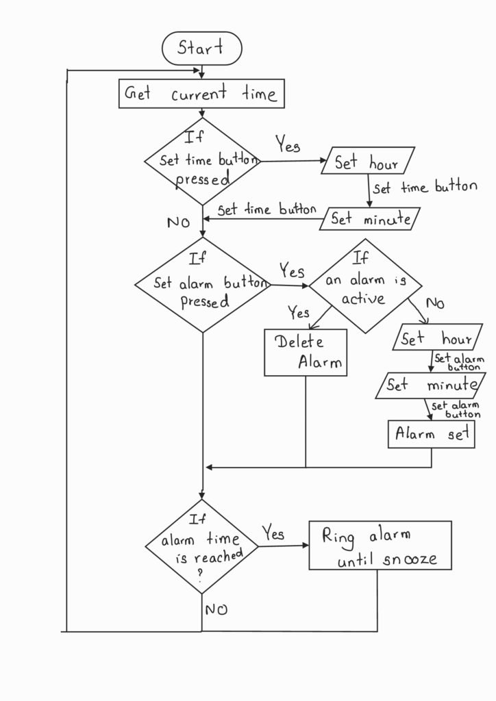
First, I developed the algorithm I should implement to demonstrate all the functions. I used three buttons for control and 6 LEDs as indicators and a DIP switch for inputting numbers.
- Buttons
- Set Time
- Set Alarm
- Stop Alarm
- LEDs
- Alarm Ring
- Alarm Active
- Set Time Mode
- Set Alarm Mode
- Input Hour
- Input Minute
The flow charts is as follows.
Arduino Based Implementation
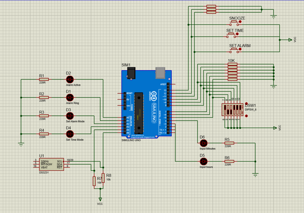
First, the code was developed in Arduino platform to test the algorithm. The source could be accessed by following this link. This was implemented on an Arduino Uno using the following components.
- Arduino Uno – 1
- RTC Module – 1
- 6-pin DIP Switch – 1
- Push buttons – 3
- LEDs – 6
- 10K resistors – 11
- 220 resistors – 6
The schematic diagram is below.
A short video demonstration of the alarm clock on Arduino is below.
AVR Microcontroller Based Implementation
After testing the algorithm on Arduino, the firmware was written for ATMega328P microcontroller using Microchip Studio. The Arduino Uno was replaced by the microcontroller itself and it’s backing components. The RTC module was replaced with the DS3231 RTC IC itself. This IC communicates with the microcontroller through the I2C interface. The code was written in a modularized way, using functions and grouping those functions into a header file. The main reason for writing the functions into a header file was to make it reusable in the final product development. Object oriented programming was used to make the program versatile.
Three classes were created with their own variables and methods. The classes are
- Time
- DS3231
- Alarm
Class Time
This class consists of the following set of variables that define the Time/Date. A single constructor method exists to create an instance of class Time.
| Hour | Year |
| Minute | Month |
| Second | Day |
Class DS3231
This sub-system interacts with the RTC DS3231 IC to maintain the timekeeping. As aforementioned, the microcontroller communicates with this IC through I2C communication. This class contains the variables and methods required for that purpose and the functions for setting/reading time and date to/from the registers of the RTC IC.
The following necessary set of functions that interface the I2C communication and encoding/decoding functions were written.
| Function Name | Task Performed |
| begin | Initialize pins and bit rate and enable TWI |
| burst_read | Send address to start reading and read from that address |
| write_register | Send address to write value and write to that address |
| decode | Convert hex representation to integer value |
| encode | Convert integer value to hex representation |
Then these functions were used to write the following functions to be used in the timekeeping.
| Function Name | Task Performed |
| set_Time | Write time to necessary registers in the IC |
| set_Date | Write date to necessary registers in the IC |
| get_Time | Read Time/date from registers and return the time as an object of Time |
| get_TimeStr | Return a string of time |
| get_DateStr | Return a string of date |
Class Alarm
A class of alarm was created to enable multiple alarm within the alarm clock. This class consists of the following four variables.
- Hour
- Minute
- Active
This class has the following methods that configure the alarms.
| Function Name | Task Performed |
| set | Set an active alarm |
| delete | Delete the current alarm |
| ring | Ring when the alarm time has reached |
Using the above three classes, five central functions were written to perform the following tasks.
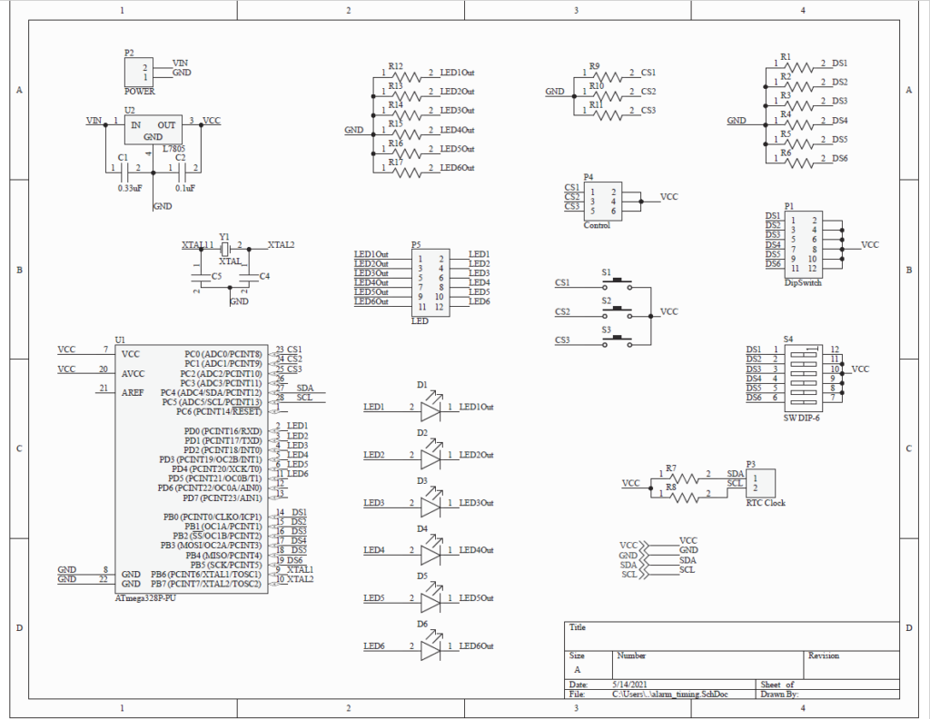
The main function was written based on the above classes and methods. The source could be found by accessing the link here. The code was tested on Proteus software based on the following schematic.

After verification of the schematic and the components, a printed circuit board for the microproduct using Altium. SMD components were used whenever possible to reduce the form factor of the PCB. The schematic and the PCB layout is given below.

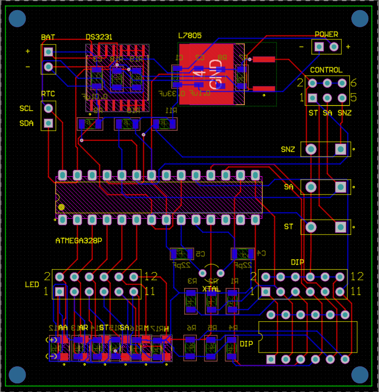
Several key factors were considered during the design of the PCB.
- LEDs and pushbuttons were embedded into the PCB with additional headers to be used to draw wires to those components when they are integrated into an enclosure.
- The components were labeled to ease the soldering process.
- A backup CR2032 coin-cell battery was added to supply power to the RTC IC to keep it running even when the main supply is cut off.
- Routing done in two layers.
The Altium project folder can be viewed from this Google Drive link.
The printed circuit board was manufactured by JLCPCB from China. The components were purchased from Arrow Electronics and were hand soldered to the PCB by Pahan Mendis. The fabricated PCB is shown below.
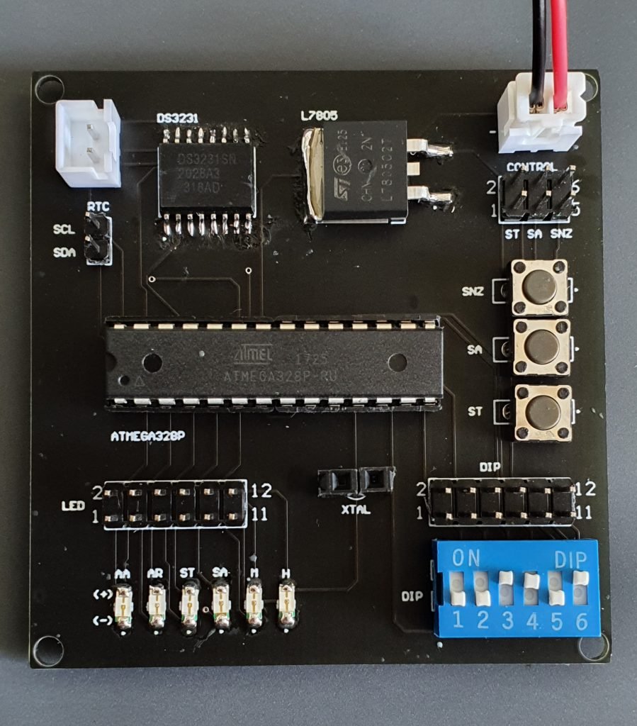
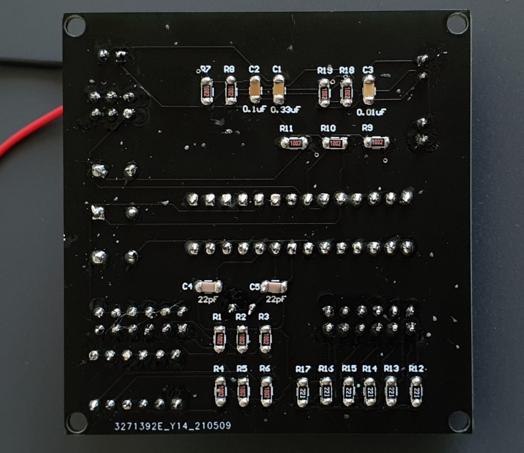
A video demonstration of the PCB is below.
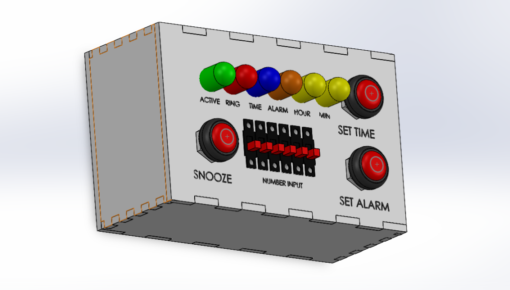
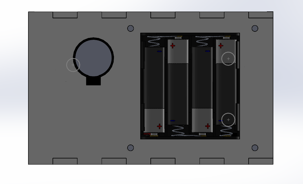
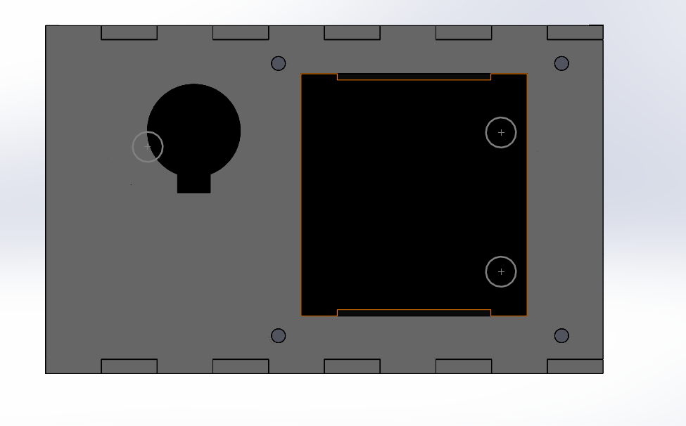
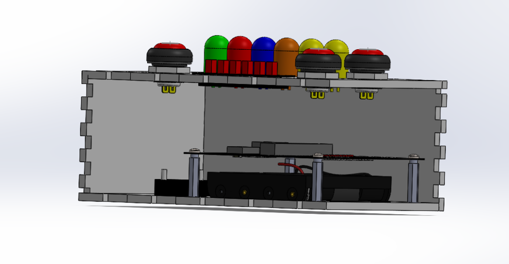
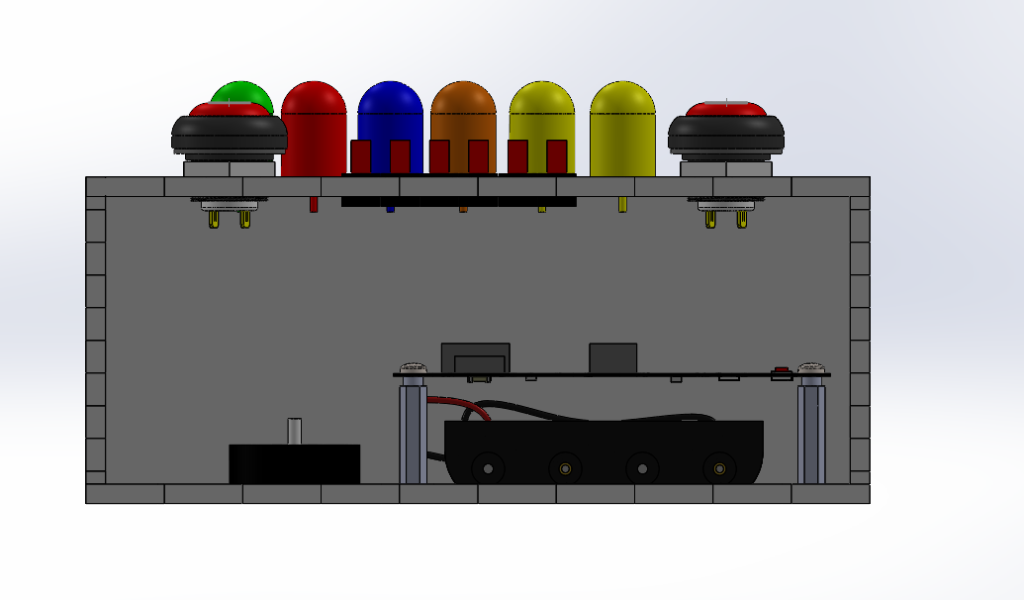
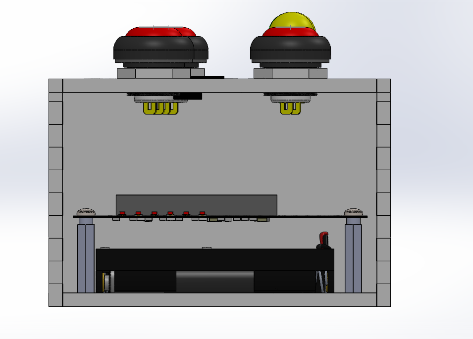
Lastly, an enclosure for the stand-alone microproduct was designed using Solidworks. The project folder can be accessed from this Google Drive link. A battery holder was embedded into the enclosure to make the product complete. The outer shell was designed with interlocking edges to be made out of acrylic or wood.
The microproduct development was successful. The next task was to design the complete product using the modular firmware developed in this stage. Read this blog post about the complete product development.
One Reply to “Design of an Alarm Clock – Microproduct Alarm Timing”