Field Programmable Gate Arrays (FPGAs) are emerging as the future trend of embedded systems. They offer high performance in executing a custom-tailored process. A system builder is a great tool the designer can use to configure these FPGAs. In this blog, I will talk about
- Why use a system builder?
- General steps of installing a system builder for any FPGA
- A detailed example of generating configuration files for Altera DE10 Lite
Why do we need System Builder to program FPGAs?
The normal procedure of writing a program for an FPGA is, you write the design code in a hardware description language and assign each input/output variable to an external pin on the FPGA. As FPGAs have lots of I/O pins, it can be troublesome to make assignments to all those pins manually. Even in a case we are going to assign them manually, we will have to know the I/O standards and development board configurations used by the particular vendor of the FPGA that we are using. As FPGAs are very fragile devices, making a wrong pin assignment or violating an I/O standard could result in damages to the chip.
To make this process easier, the FPGA development kit vendors came up with system builders that generate configuration files according to the standards. System builders generate, what we call, a project configuration file with assignments to external pins that you require in your project.
For an example, assume you want to turn on an LED on the FPGA development board. In the conventional way, first you would have to define an output variable ‘LED1’ and write the Hardware Descriptive Language (HDL) code for lighting it. Then you would refer the datasheet of the FPGA that you are using and find out the pin that is connected to the LED on the development board. You should then assign that ‘LED1’ variable to that pin manually acoording to the I/O standards.
To avoid all this hassle, System Builders automatically generate a project file with pin assignments for the components that you use in your project. For the above example, the System Builder file will contain the ‘LED1’ variable already assigned to the pin that is connected to the LED on the development board. All you have to do is, get the variable name from this configuration file and write the algorithm for that component. These are great for beginners as they let us focus on our digital design process rather than worrying about configuring the FPGA correctly to implement that digital design.
General steps of using a System Builder
1. Find out the respective system builder for the FPGA that you are using.
2. Install the system builder on to your computer.
3. Open the installed software and select the required configuration options.
4. Generate the configuration files and save it on a location of your choice for further use.
Creating a system configuration with DE10 Lite
PART 1 – Downloading and Running the System Builder
1. Download the System Builder.
The system builder can be found by a simple search on the internet by specifying the development kit model.
After finding and downloading the respective system builder for your FPGA development kit ( in this case Terasic DE10-Lite System Builder) you’ll see the file on your downloads folder.
1. Download the zip folder

2. Extract the folder DE10-Lite_v.2.1.0_SystemCD.zip

3. Open the DE10-Lite_v.2.1.0_SystemCD

4. Open the Tools Folder

5. Open the SystemBuilder Folder

6. Run the DE10_Lite_SystemBuilder.exe

PART 2 – Introduction to the System Builder.
The system builder GUI will guide you through the necessary steps of creating a configuration file.
You should generate a configuration file through the System Builder when you starting on your project.
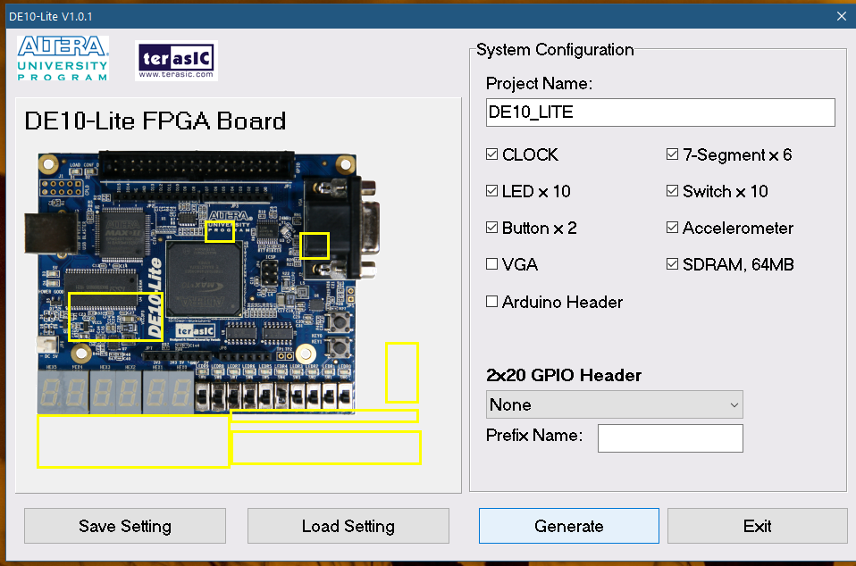
1. Change the project name as required.
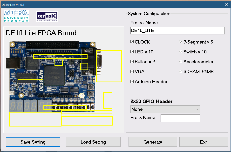
2. Click on the check boxes to select the required configuration.
Select the components that you will be using in your project.
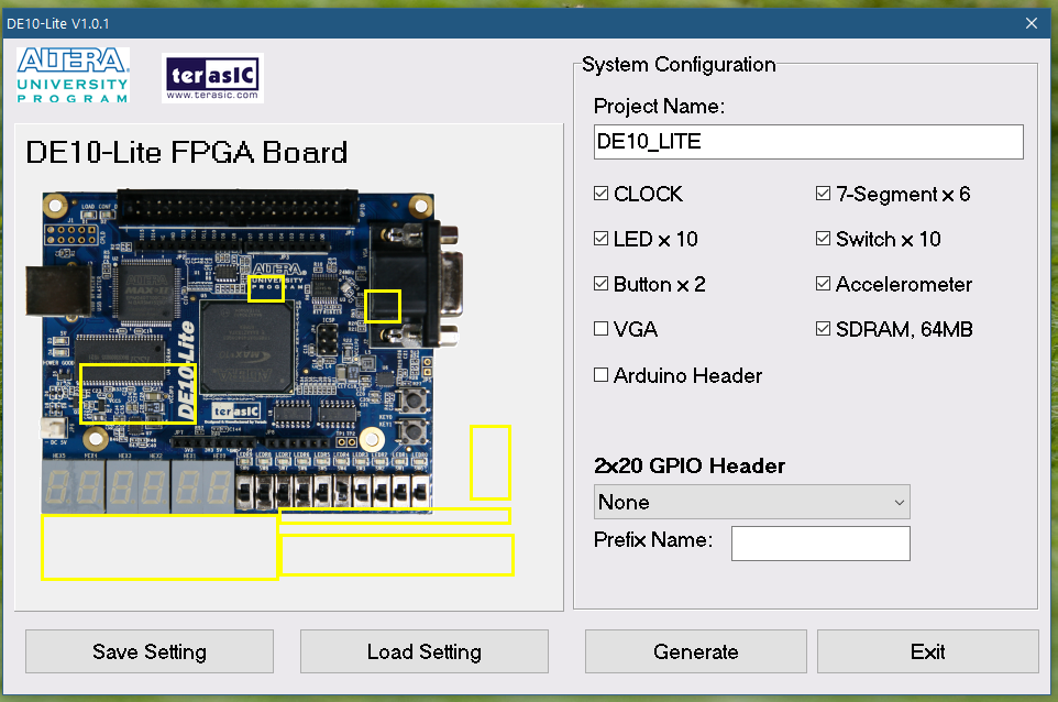
3. Click on Save Setting to save your configurations.
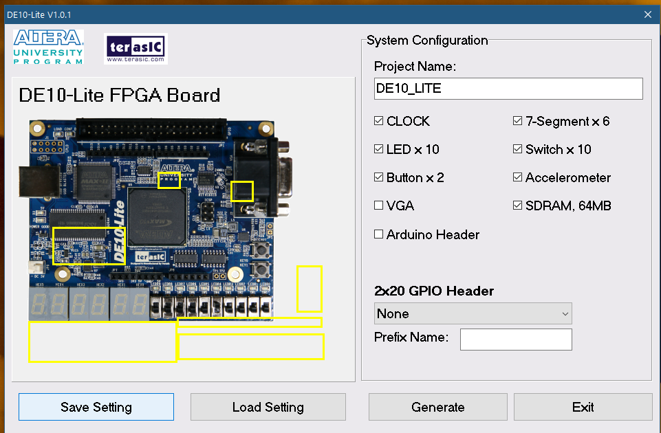
4. Browse to your preferred location and save the .cfg file
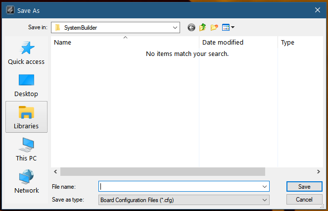
Also you can click on Load Settings to Load previously saved configurations.
Without selecting the components again, you can load configuration files that have been saved as above, from your computer. Click on Load Setting and browse for the required .cfg file and open it.

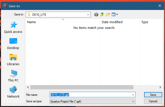
5. Press Generate to generate a Quartus Project File (.qpf) file that can be used as the base for your FPGA project on Quartus Prime.
6. Browse to the project location and save the .qpf file
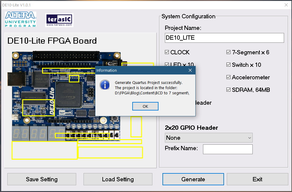
7. You will be prompted with a message when you successfully created your Quartus Project
When you browse to your project location you can see that these files has been created
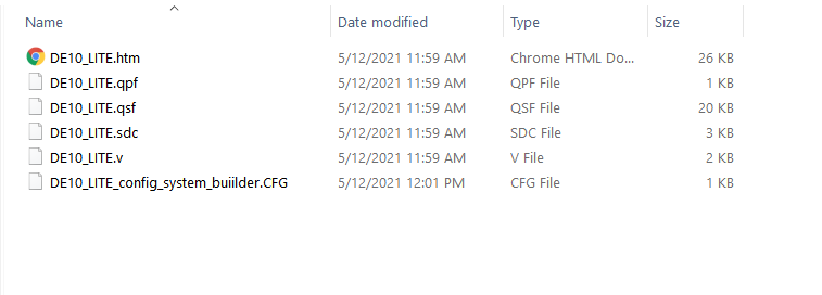
PART 3 – Opening the Quartus Project File
To open the project file you just created, you can follow two methods.
Method 1 – You can locate the .qpf file and double click to open it with Quartus Prime.
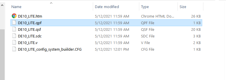
Method 2 – If not, you can launch Quartus Prime and open the project from there.
1. Open Quartus Prime
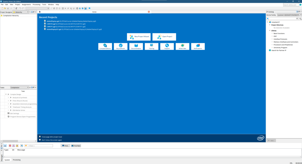
2. Click on File->Open
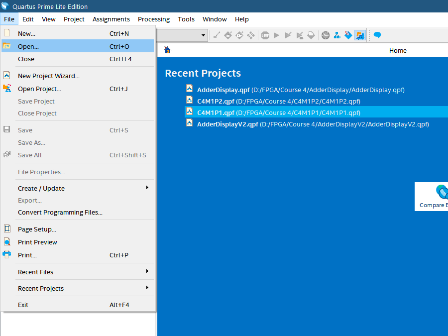
3. Browse to the location of the Quartus Project
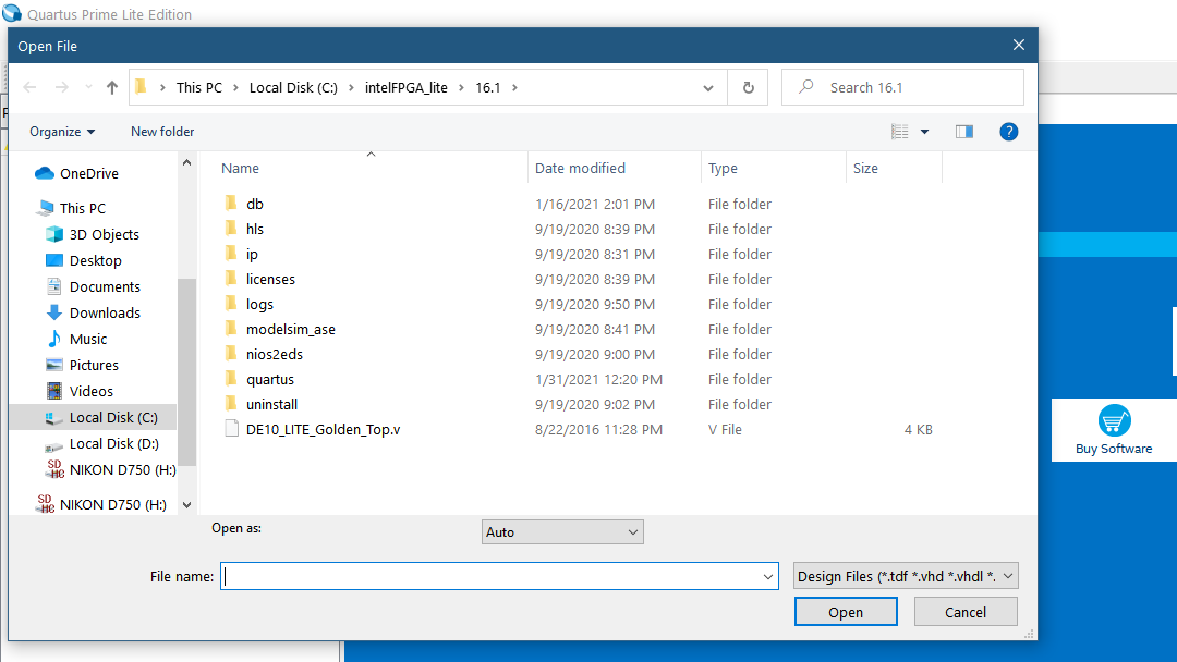
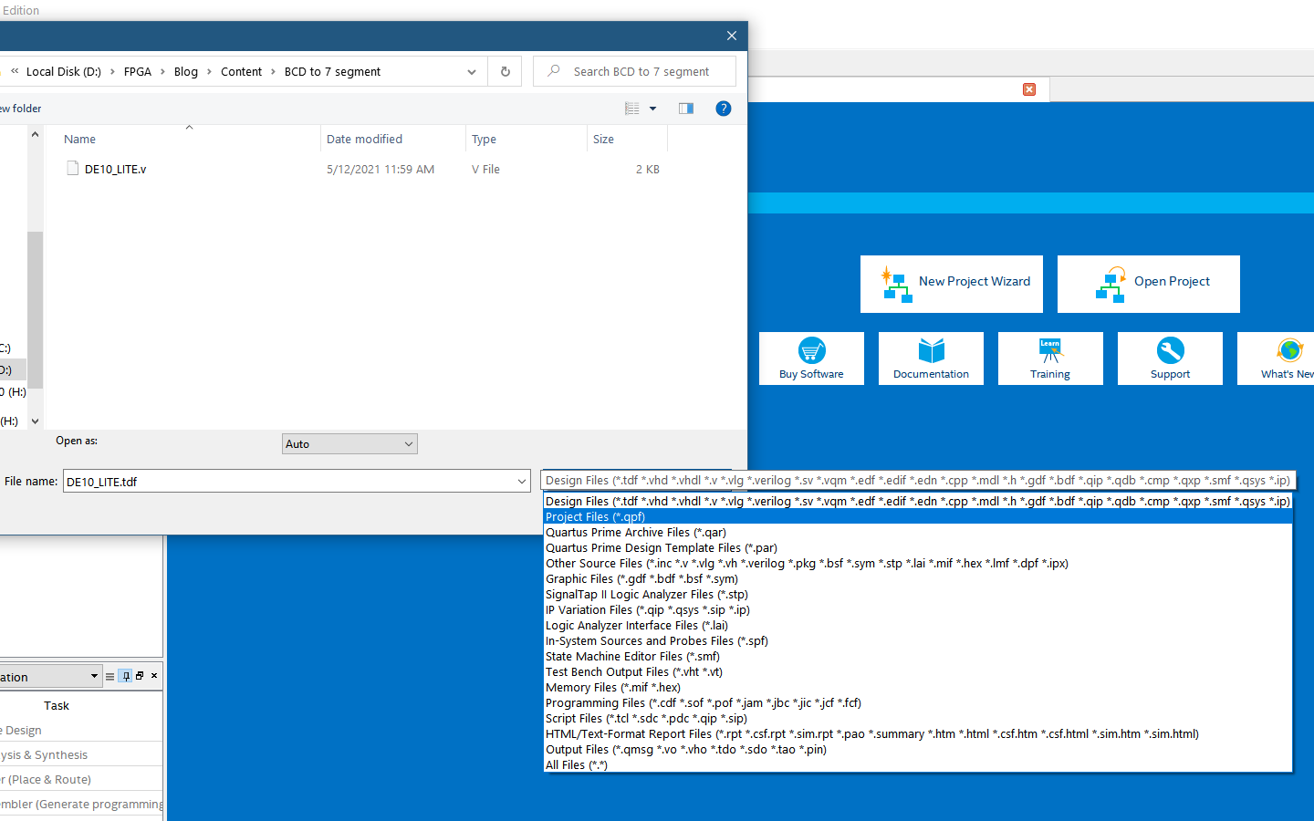
4. Select the file extension as Project Files
This will easily filter out the .qpf file we need.
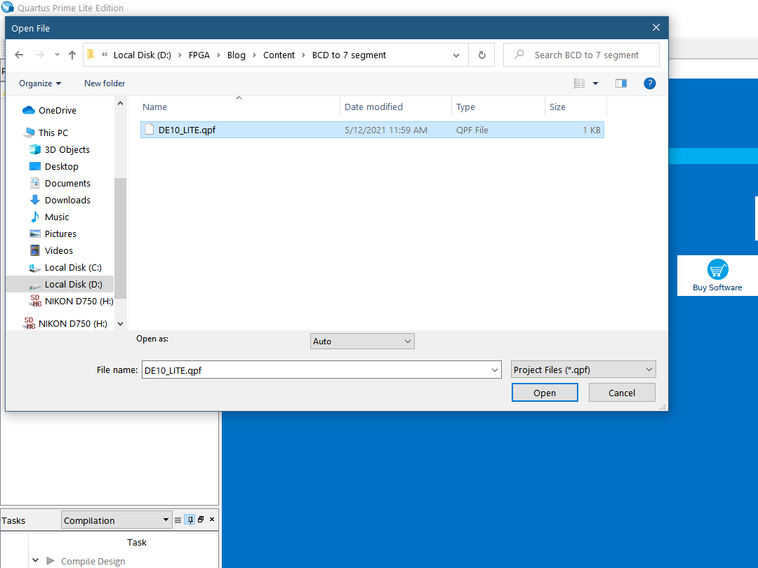
5. Select the .qpf file and click open
Congratulations!! now you have opened your Quartus Prime Project

To view the files in your project click on Files from the dropdown menu in Project Navigator
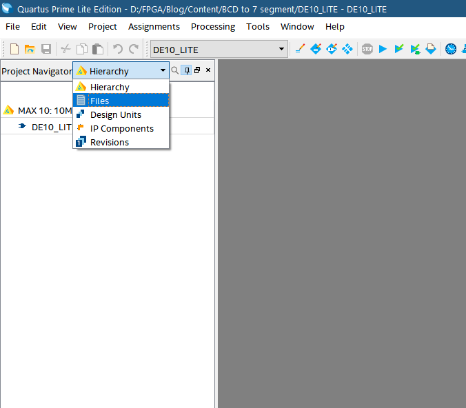
You can see the files on your project from the list
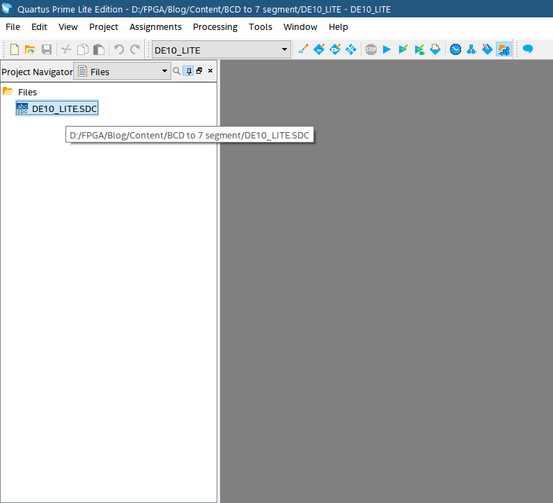
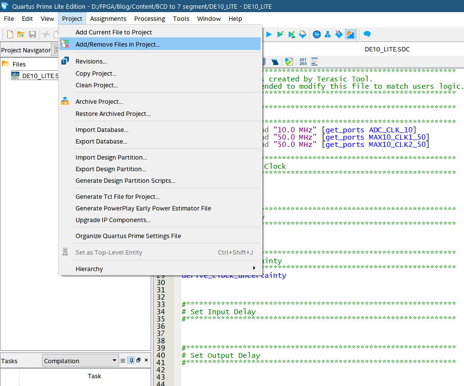
All the required .v files might not have been added to the project yet. You can add them by following the method below.
1. Click on the Projects tab and select Add/Remove Files in Project…
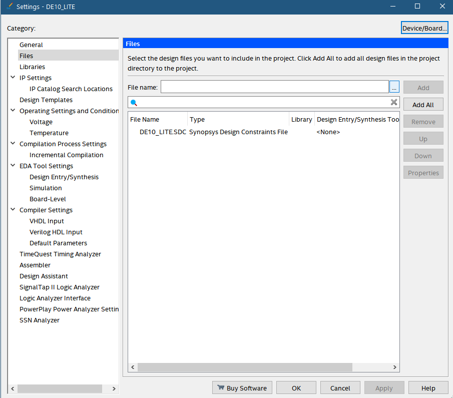
2. Press on the … to browse the files
3. Browse to the file location and select the required design files.
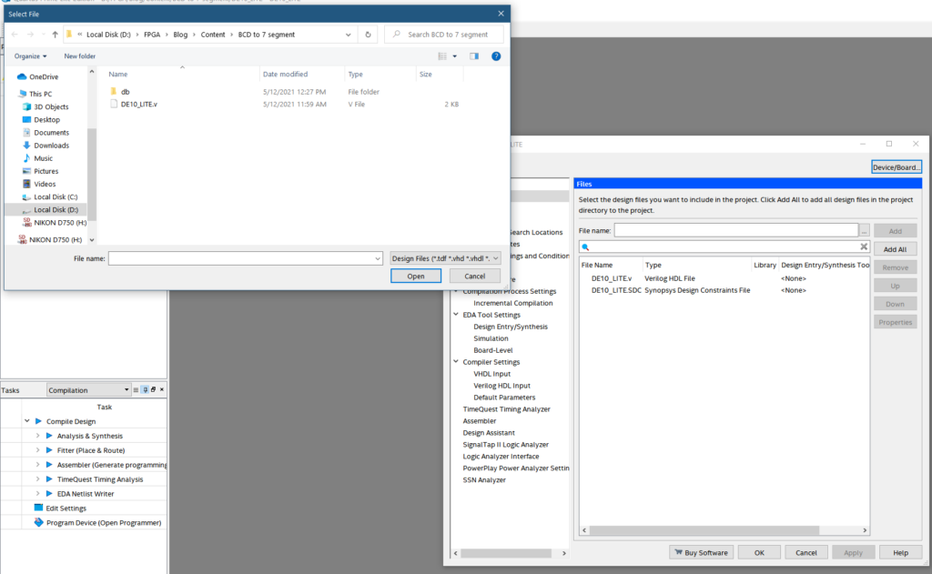
4. You can see the files appear if then click on Apply to finalize
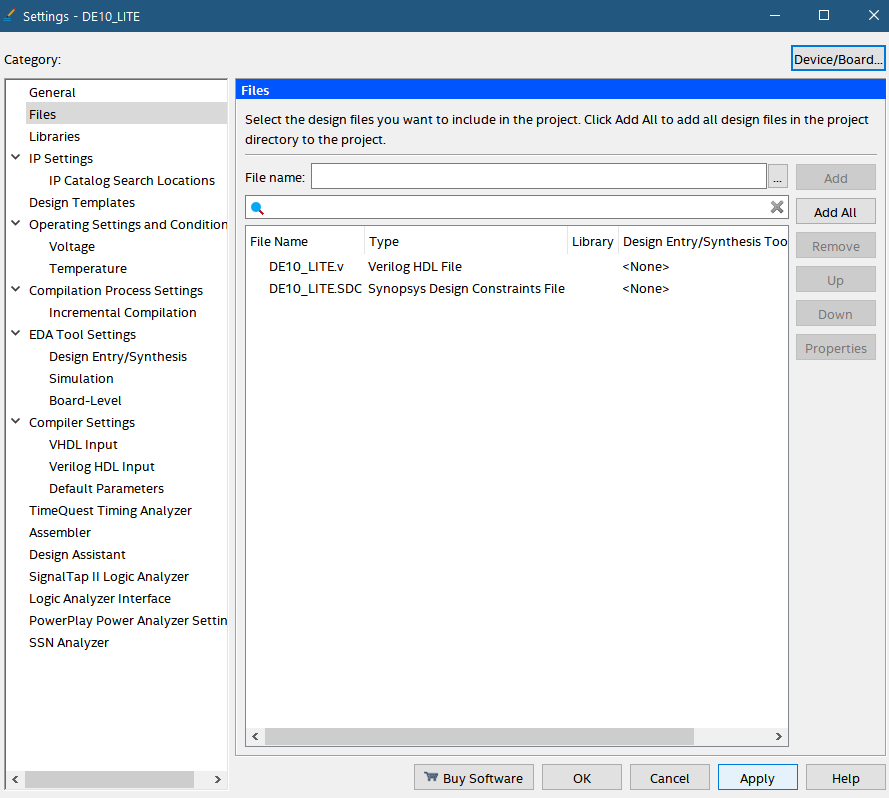
5. Click on OK to close the window
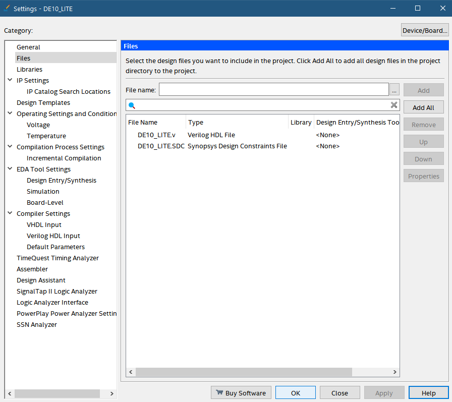
6. Go Files in project navigator and click on the file to view it.
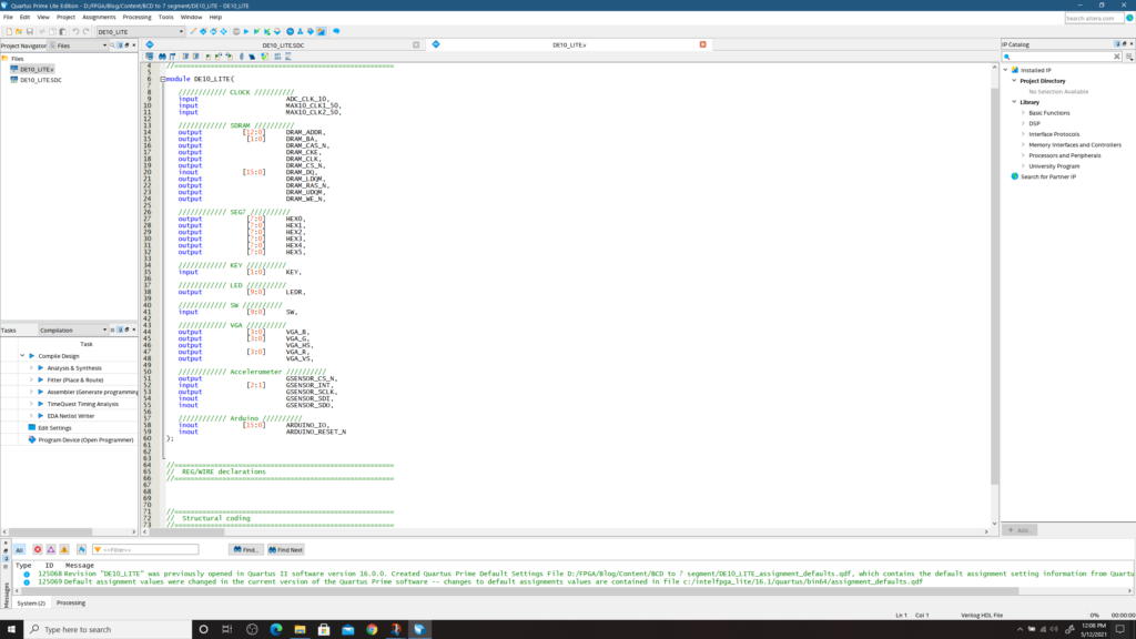
You can view this .v file generated by the System Builder that contains all the pin assignments you may need. You can now write your design file in a hardware description language by referring to this.
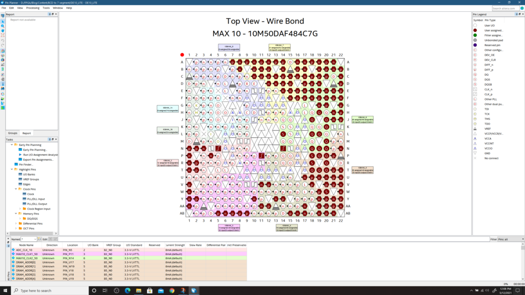
Now we will check whether the device details and the pin assignments are correct.
1. Click on Assignments > Pin planner to see all the pins assigned automatically
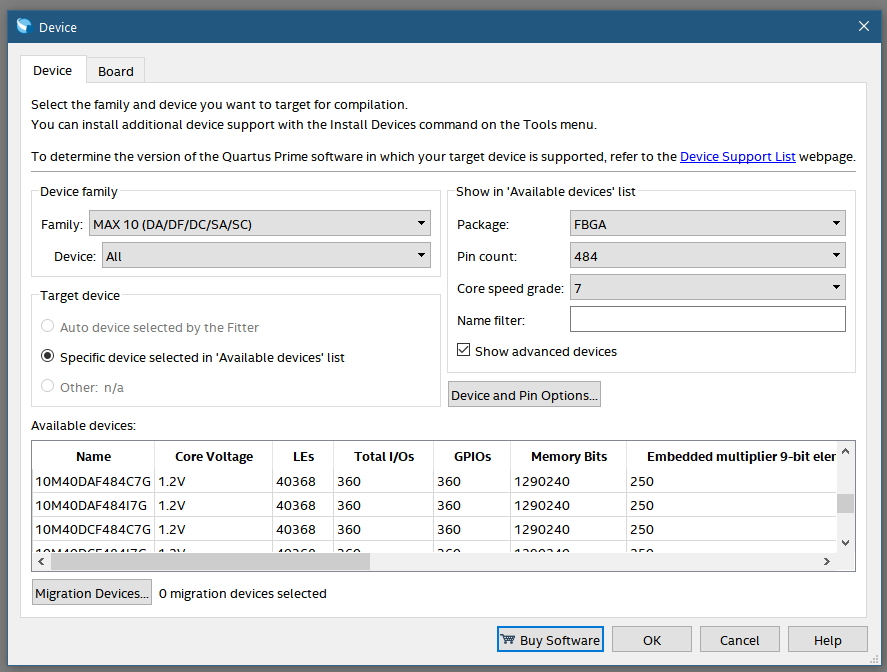
2. Click on Assignments>Device to see the device details
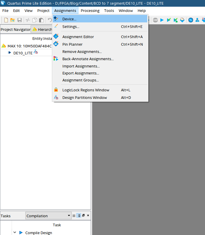
Here you can see all the Chip details already added automatically. Easy Right?
