

This post will demonstrate how to use Atmel Studio/Microchip Studio and USBasp to program an AVR microcontroller to blink an LED.
Blinking an LED is not the coolest project but it is simple and it can help you verify the procedure of programming an AVR microcontroller before you start getting fancy.
Even though there are many tools you can use to program an AVR microcontroller, Atmel Studio/Microchip Studio as the IDE and USBasp as the programmer are the best and cheapest for beginners. If you want to know more about these tools and how to get them ready, read this blog post first.
Step 1 – Writing the code
In this project I have used Atmel Studio/Microchip Studio to write for ATmega328p to blink an LED. To learn more about the basics of writing code for AVR microcontrollers using AVR C++, click here. For now, I have included the code to blink an LED.
Here is a step-by-step guide on how to generate output file for writing onto the microcontroller.
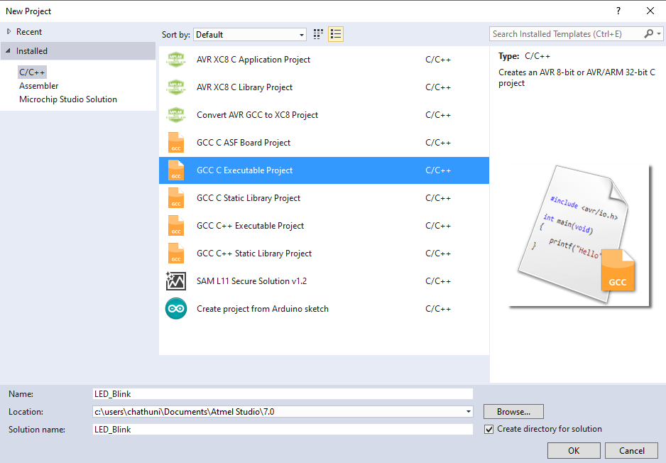
Open Atmel Studio/Microchip Studio and select New Project.
Select GCC C Executable Project as the project type, name your project and press OK.
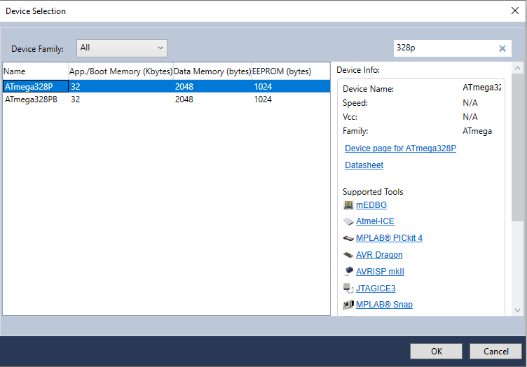
Next, select your microcontroller from the Device Selection Toolbox and press OK.
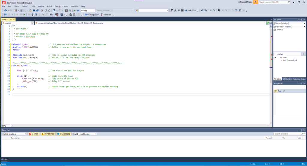
A blank text editor will appear. Type the following code to blink and LED at Port C-Pin 5.
#ifndef F_CPU			// if F_CPU was not defined in Project -> Properties
#define F_CPU 1000000UL			  // define it now as 1 MHz unsigned long
#endif

#include <avr/io.h>			  // this is always included in AVR programs
#include <util/delay.h>			  // add this to use the delay function

///////////////////////////////////////////////////////////////////////////////////////////
int main(void) {

	DDRC |= (1 << PC5);		  // set Port C pin PC5 for output

	while (1) {	                  // begin infinite loop
		PORTC ^= (1 << PC5);	  // flip state of LED on PC5
		_delay_ms(500);		  // delay 1/2 second
	}
	return(0);	// should never get here, this is to prevent a compiler warning
}
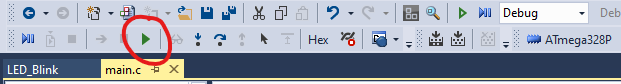
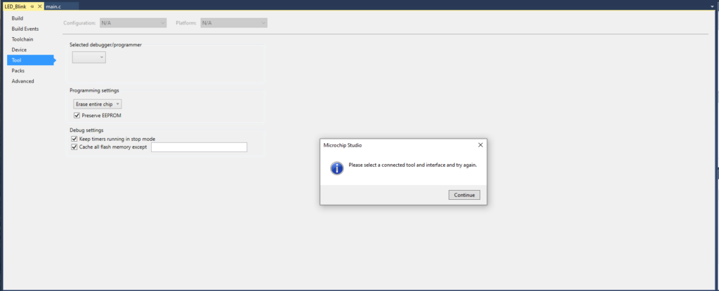
Press the green color Start Debugging Button or F5 to compile the code.
This dialogue box will appear. Press Continue for now as we are not using the in-built programmer for this project.
Now you can navigate to the project folder. By default, this will be inside the folder called Atmel Studio/Microchip Studio in Documents. Locate the .hex file inside the <Project_Name>/Debug

Now we will see how we can upload this .hex file to the microcontroller.
Step 2 – Setting up the Programmer
We will use USBasp programmer to upload the output file to the microcontroller. For that, there are several connections that should be made between the programmer and the microcontroller and the programmer and the computer.
The following connections should be made between USBasp and the microcontroller, in this case ATmega328P.
| USBasp | ATmega328P |
| MISO | PIN 18 – MISO |
| MOSI | PIN 17 – MOSI |
| SCK | PIN 19 – SCK |
| RESET | PIN 1 – RESET |
The VCC on the USBasp should be connect to 5V DC and GND should be connected to the same ground as that of the microcontroller.
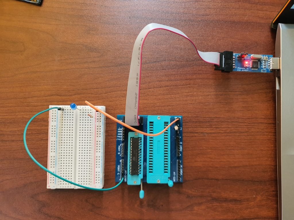
You can place the microcontroller on a breadboard and make these connections or use a development board. Using a development is way more easier as you do not have to make these connections every time you want to program the MCU and you don’t end up with wires all over. You can just insert the MCU into its slot, plug in the programmer and start uploading. We have designed a development board for ATmega328 and ATmega32 ourselves. To learn more and make/get one for yourself, click here.

Here is the USBasp programmer attached to my development board.
Now all we have to do is burn to code into the MCU through the programmer.
Step 3 – Uploading the output file
Plug the programmer to the computer through the USB port and open Extreme Burner.
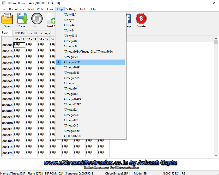
Select the microcontroller from the Chip menu on the menu bar.
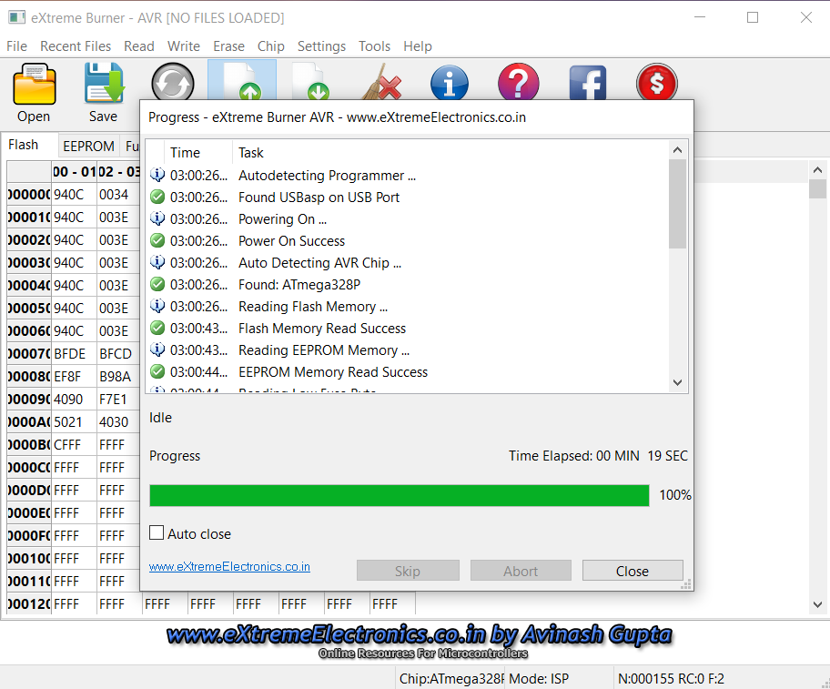
Press Read All button to confirm correct connectivity. If the programmer reads the current memory of the microcontroller successfully, congratulations!, the connection are correct. If not, check the connections again.
Then press Erase Chip button to erase the current memory of the microcontroller before uploading the output file.
Click Open and use the browse window to locate the .hex file mentioned above and click OK.
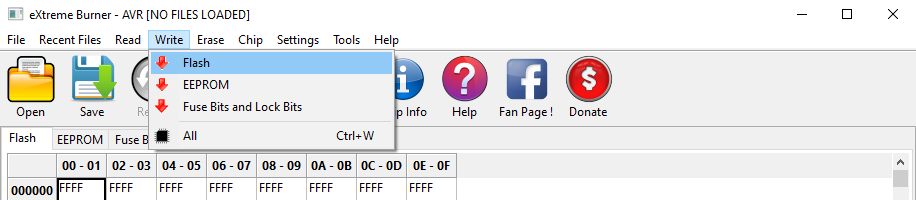
Go to Write menu on the menu bar and press Flash.
That’s it! the microcontroller will now be blinking the LED connected to PIN C5.
Now you can write any code to perform any task you want by the microcontroller and follow this method to upload and run it.
3 Replies to “Programming AVR microcontroller using Microchip Studio and USBasp”