
We designed an automatic switch that can be controlled via Wi-Fi to connect electrical appliances to power. Our design is similar to a plug top to which the user can easily connect the wires of his/her electrical appliance, plug into the power socket and switch it on/off using an web or mobile app over Wi-Fi. This was designed is parallel with the Advanced PCB Designing and Fabrication Workshop organized by the IEEE Student Branch of University of Peradeniya.
Project Members
- Pahan Mendis
- Chathuni Wijegunawardana
Advisors
- Kithmin Wickramasinghe
- Iresh Jayawardana
We mainly focused on the PCB and the hardware design while we were developing this Smart Brick. We have not developed the software interface
PCB Design
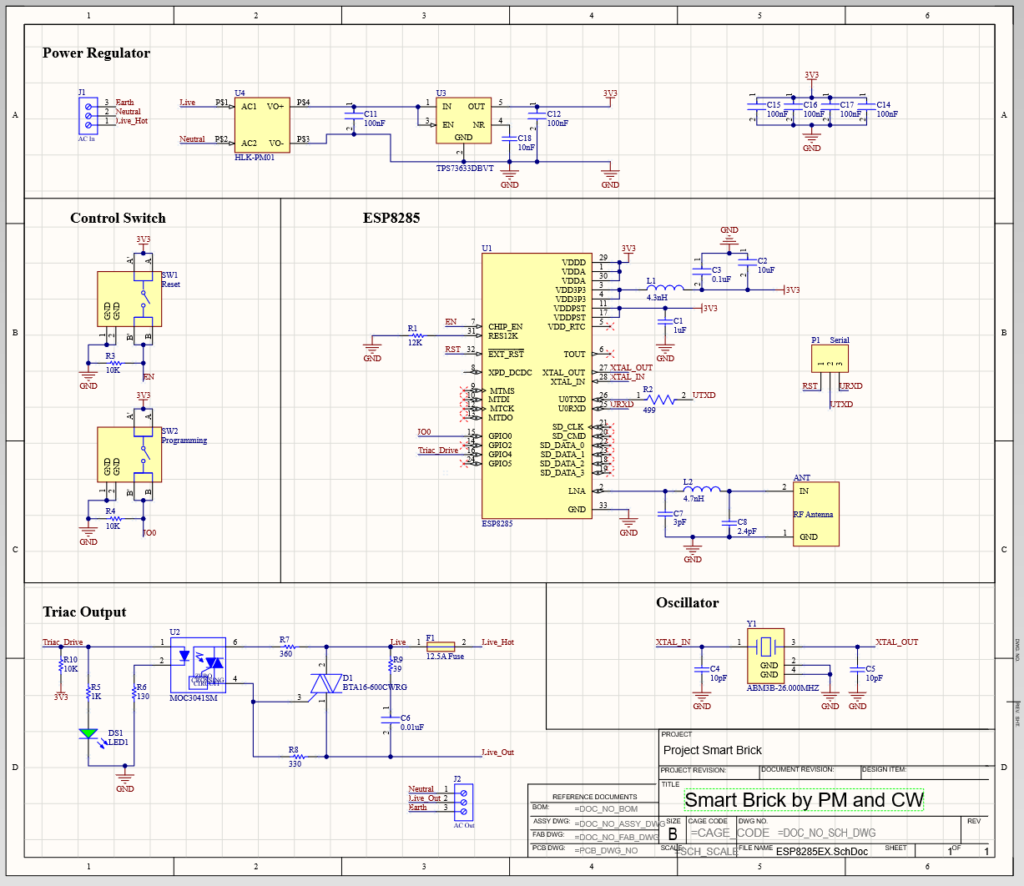
The 2-layer PCB was designed using Altium Designer. We used ESP8285 Wi-Fi SoC to as the central controller of our design. A triac-optocoupler circuit was used for the switching instead of a conventional relay circuit to increase the efficiency and lifetime and avoid the noise otherwise produced while a relay is switching.
The following key aspects were considered while we were designing the PCB.
- The size of the PCB was minimized to decrease the size of the Smart Brick.
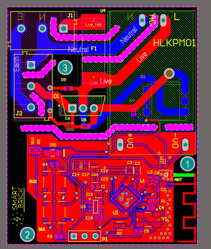
- The AC and DC sections of the PCB were positioned separately on the same PCB. The cross talk between these two sections were removed and isolated using board cutouts.
- Track widths of the routes were calculated according to the current and expected power dissipation. The solder mask over these routes were removed to pour solder on them to reduce power loss.
- Cutouts were placed in between live, neutral and ground wires to avoiding voltage arcs.
- A fuse was placed to provide protection to the circuit and the electrical appliance.
- The connectors were positioned to make the wiring easier, taking our physical design of the Smart Brick into consideration.
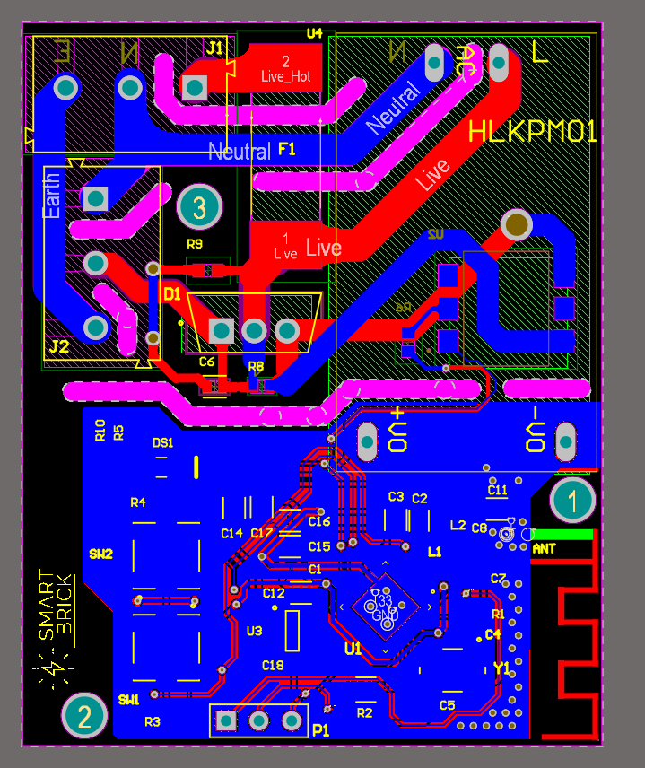
- A Meandered Inverted-F Antenna was designed and placed on the PCB for communication according to the specified spacing.
- Copper pour was applied on the low voltage section. Via stitching and teardrops were applied as well.
- The circuit and layout guidelines in the datasheets of the main components were followed.
- The PCB was designed to obey the PCB manufacturer’s rules and capabilities.
PCB Schematic
PCB Layout
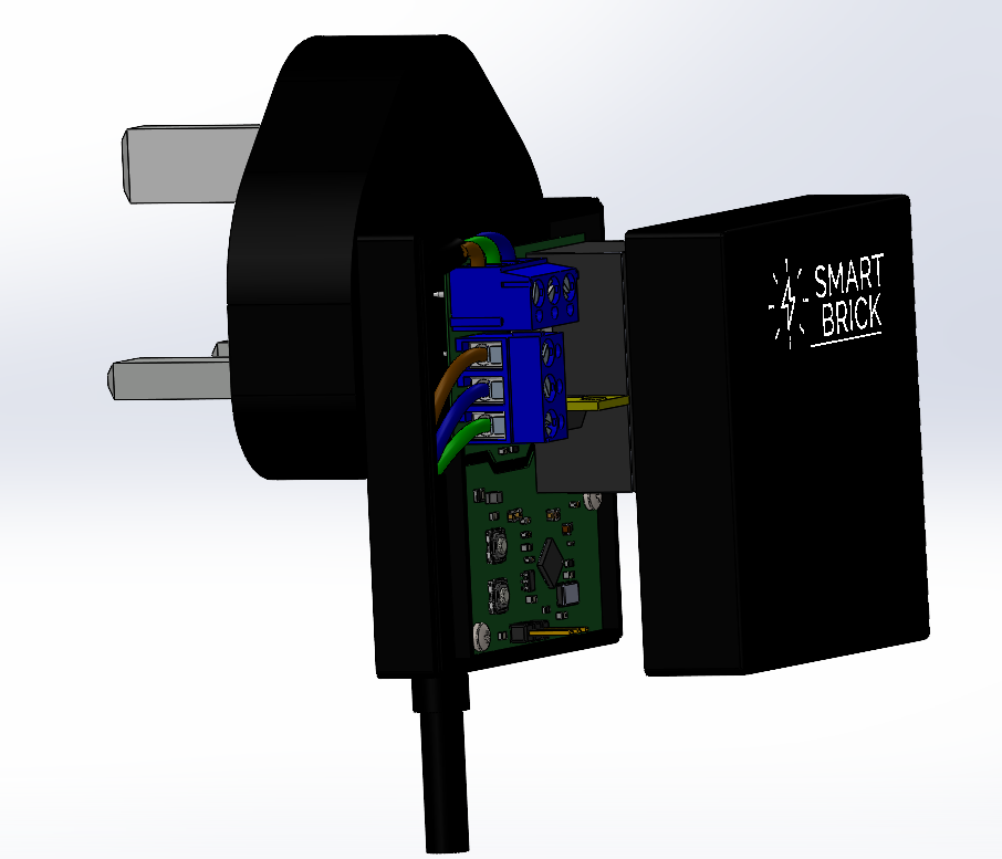
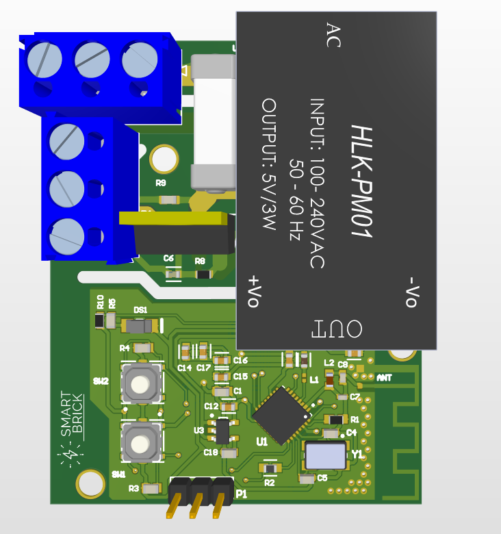
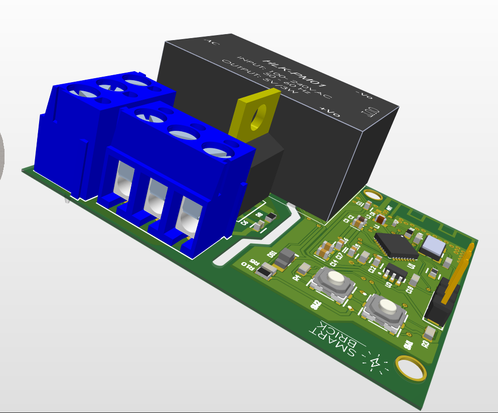
The 3-D view

Conceptual Design
The physical design of the Smart Brick is a plug top that replaces the plug top of the electrical appliance. This was designed such that the user can easily remove the current plug top and connect the wires to our Smart Brick. The PCB was designed to suit this physical design. Wire guides were placed inside the casing of the PCB to neatly manage the wiring. A 3-D model was designed using Solidworks.