How it came to be
Back in October 2022, we initiated a component bank under the SLRC branch of the Electronic Club. Our goal was to gather a set of electronic and robotics components and modules from our seniors and through the E-Club funds that the ENTC students can borrow and use for their projects. This component bank initiative has been an idea within the department for a long time and became much needed as most electronic modules and components were unavailable in the local store after the economic crisis, and import bans hit.
Under the guidance and motivation of Dr.Ranga Rodrigo and Dr.Peshala Jayasekara, we initiated this project, purchased a bunch of components like Lipo batteries and chargers, and collected some valuable parts from our seniors. Our target was to gather a set of essential components for the level 2 students to build their robots in the Robot Design and Competition module.
But there was a significant barrier that we needed to overcome. The 25D Pololu motors already in our department needed motor driver modules that can support high currents up to 5A per channel. However, by then, the major manufacturer of the motor driver that was available in the market, had temporarily stopped producing these motor drivers as the IC used in their design had gone out of stock in the international market. So we searched international sites to see if we could purchase a motor driver from overseas for a reasonable price. The only available option was the Pololu VNH5019 motor driver, which could provide 12 A per channel. But it was priced at $120 (Rs.43,000), which was too expensive and an overkill for our current requirement. Most other compatible motor drivers, such as the SparkFun Monster Moto Shield, have gone out of production, mainly because of the chip shortage.
That was when we thought…..
Why not design one ourselves?
Getting things started
We started looking for a motor driver IC that was still in stock and reasonably priced. We found the DRV8256PPWPR(PWM version) and DRV8256EPWPR(E version) ICs from Texas Instruments to be ideal for our design. Since the E version of ICs control mechanism was identical to our familiar motor drivers which also had enough in stock by that time, we decided to go with it.
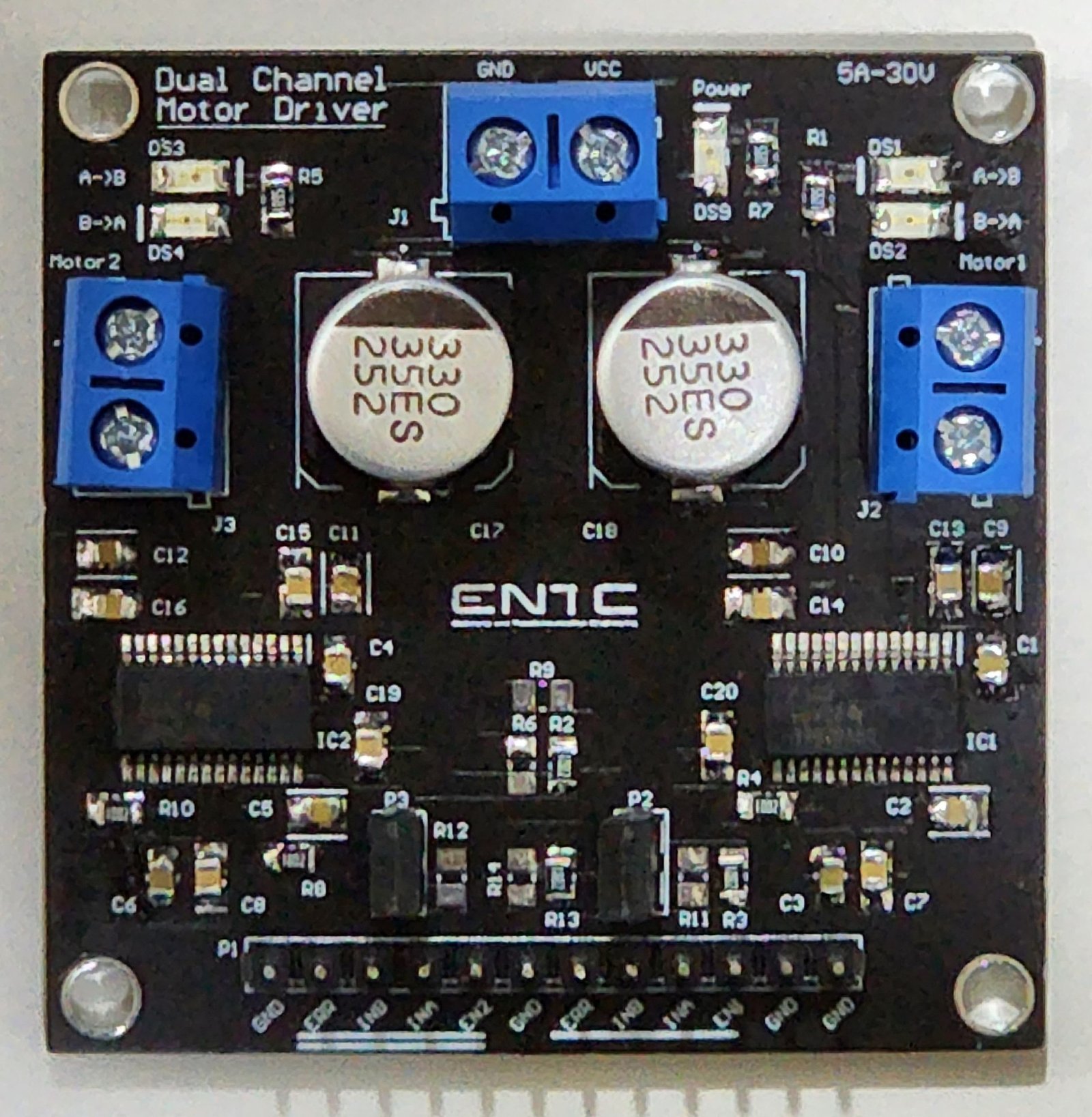
We didn’t want to stop halfway. We aimed to produce a professional, adaptable, and marketable motor driver that the students can confidently use for many years. So, we decided to go for a professionally fabricated PCB with SMD components and a small form factor.
Through thick and thin
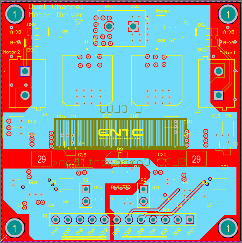
We designed the PCB according to the guidelines provided in the datasheet on Altium Designer. The PCB has 4 layers, with the middle layers for power and ground, and proper precautions to ensure signal and power integrity.
We sent out the 1st batch for fabrication to JLCPCB in December 2022. In addition, we purchased a small set of components from Mouser Electronics to assemble and test this batch.
After testing this PCB, we identified some mistakes, corrected them on the PCB design, rechecked everything with the datasheet, and sent out a second test batch for fabrication after two weeks. To much of our delight, the motor driver module was functioning perfectly as expected. Of course, we were not expecting to spend more of our money and time on mistakes.

Now, we were ready to fabricate the PCBs for the department and purchase the components. The Robot Design and Competition was only around a month away.
But…
The motor driver IC has gone out of stock.
Luckily, the PWM version was still in stock, and we were glad that we ordered two ICs of that version in our Mouser order, just in case. We quickly checked the compatibility; the pin layouts were compatible, but the control mechanism differed. Finally, we tested a new PCB with the PWM version of the IC and the new control mechanism, and it worked.
So, we sent out the PCB for fabrication from JLCPCB. We also ordered the components worth Rs.170,000 from Mouser Electronics. We had support from the E-Club funds and Dr.Ajith Pasqual.
Assembling
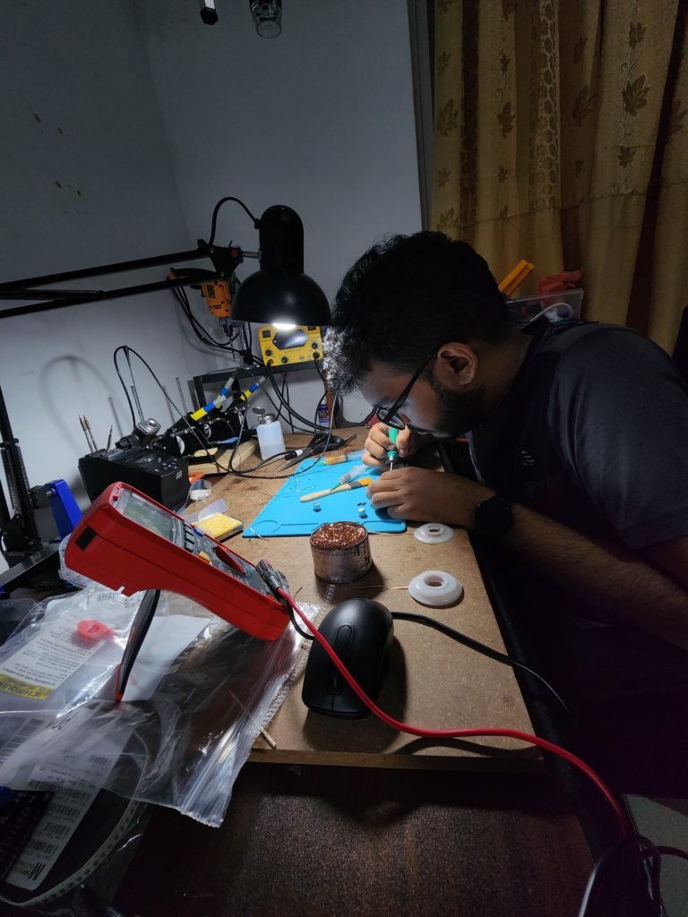
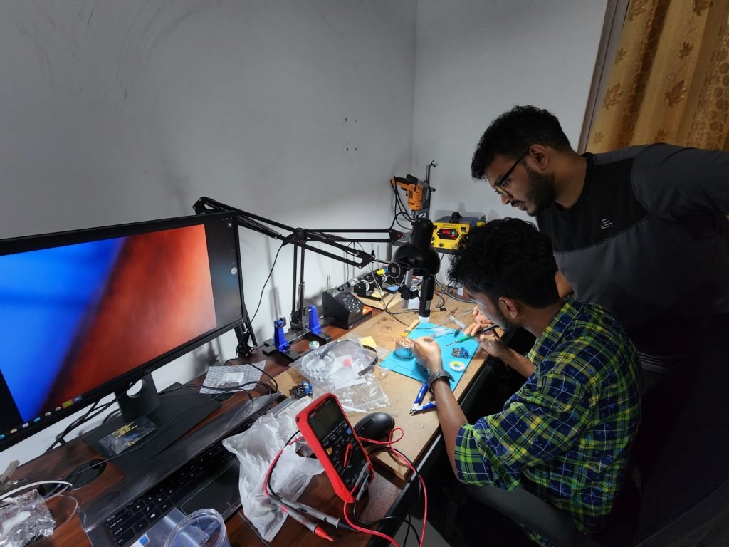
It was impossible to get the PCBs assembled by JLCPCB as it would cost us a lot. So, we took on the challenge of soldering all the PCBs ourselves. We were looking at one or two sleepless nights, but it was okay; we enjoyed doing this for the department.
The challenging part was to solder the motor driver IC which was very small. However, it was a learning opportunity.
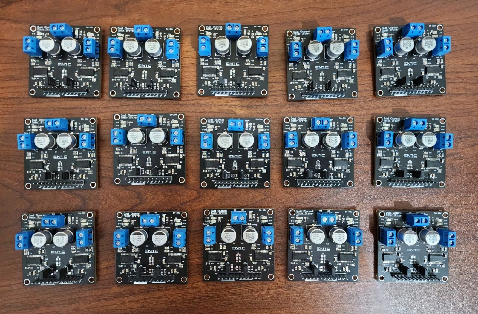
After one sleepless night and two full days, we assembled 17 motor drivers and tested them.
This is the User Guide that Chamindu prepared for this motor driver.
Features
- Dual H-bridge driver
- 4.5V to 50V operating voltage range
- 6.4 A maximum continuous current rating per motor
- Thermal shutdown and overcurrent protection
- Enabling and disabling two motors separately using jumpers
The total cost of the ENTC dual motor driver module came to be $17 (Rs.6300). The other motor drivers available in the market cost more than $45. We could save around Rs.200,000 by manufacturing 20 PCBs ourselves rather than buying the available motor driver in the market.
Thoughts
It was a wonderful experience to use our skills and knowledge in a valuable and meaningful way during this process. In addition, we had great support from Dr.Ranga Rodrigo with purchasing the electronic components for the PCB through the Electronic Club funds, Dr.Peshala Jayasekara with encouraging and guiding us in this endeavor, and Dr.Ajith Pasqual with purchasing the components and getting them delivered.
I am thankful to everyone that supported me, even with a word of encouragement, along the way. We will forever be content as we see students using these motor drivers in many more years to come.
The Team
| Name | Contribution |
| Pahan Mendis | Selecting the Motor Driver Designing the PCB Soldering Assembling Testing and Debugging |
| Chathuni Wijegunawardana | Creating the Schematics Testing and Debugging |
| Wikum Jayasanka | Soldering Assembling |
| Janindu Leelananda | Verifying the PCB Testing and Debugging |
| Chamindu Liyanage | Selecting the Motor Driver Preparing the User Guide |

